 Home
Home

Configuration Options :: Cage TOP and BOTTOM Geometry & Ventilation Options
Starting with version 0.50, the open ventilation areas of cages can optionally be replaced with a configurable ventilation grid. These settings do not apply for cageless faceplates created by setting the faceplate only option to a fixed height.

These settings only apply to the top and bottom of the cage proper. Separate controls are present for the sides and back of the cage. These settings do not apply for cageless faceplates created by setting the faceplate only option to a fixed height.
cage top geometry
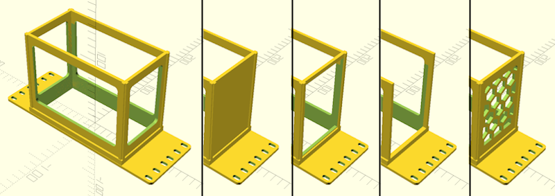
 new for version 0.7 :: This setting determines how CageMaker PRCG generates the top of the cage, which can be one of the following:
- Open Top is the default setting, which produces a largely open top with maximum ventilation area.
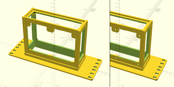
- Lidded, Open Top With Tabs & Screw Holes does what the name implies, and is intended for creating an open top that will be covered by a lid. The screw hole size is adjusted with the cage top lid screw holes setting.
- Solid Top (No Ventilation Cutout) produces a solid top without any opening. This can be used as a shelf for the space above the cage.
- Structure Only, Completely Open provides the maximum amount of open space while still generating a structurally strong cage.
- No Top At All instructs CageMaker PRCG to not generate a cage top or support structure.
- The ventilation grids select grids with the listed hole shapes.

The no top at all setting should only be used in rare situations as it reduces structural integrity. For most cases where maximum open space is desired, the structure only, completely open setting is a better choice.
cage top lid screw holes new for version 0.7 :: This setting determines the diameter of the screw holes created in the cage top for attaching a lid when cage top geometry is set to Lidded, Open Top With Tabs & Screw Holes*.
This feature requires that the cage top geometry be set to Lidded, Open Top With Tabs & Screw Holes.
cage bottom geometry
new for version 0.7 :: This setting determines how CageMaker PRCG generates the bottom of the cage, which can be one of the following:
- Open Bottom is the default setting, which produces a largely open bottom with maximum ventilation area.
- Solid Bottom (No Ventilation Cutout) produces a solid bottom without any opening. This can be used as a shelf for the interior of the cage, and is required if placing standoffs onto the bottom.
- Structure Only, Completely Open provides the maximum amount of open space while still generating a structurally strong cage.
- No Bottom At All instructs CageMaker PRCG to not generate a cage bottom or support structure.
- The ventilation grids select grids with the listed hole shapes.
The no bottom at all setting should only be used in rare situations as it reduces structural integrity. For most cases where maximum open space is desired, the structure only, completely open setting is a better choice.
cage bottom standoffs
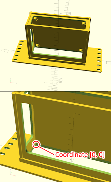
new for version 0.7 :: This setting adds screw-mount standoffs to the bottom of the cage. Coordinates (in mm) must be provided for each standoff, where the zero-Y/zero-Y point is the front-left corner of the bottom of the cage - X values extend toward the right of the cage, and Y values toward the back of the cage. Standoffs are conical in shape and are 2.5x the screw hole diameter at their tops, widening to 4.5x the screw hole diameter at the base.
This feature is not supported by the web-browser port of CageMaker PRCG running on OpenSCAD Playground, as OpenSCAD Playground does not support text entry. To use this feature, download and install OpenSCAD and run CageMaker PRCG within it.
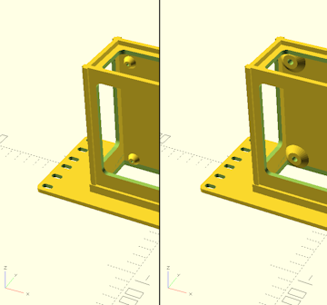
Coordinates must be provided as a series of X and Y pairs separated by commas and enclosed in a set of brackets. For example, in the sample image at right the coordinates are as follows:
[10, 10, 10, 110, 140, 10, 140, 110]
The first pair of coordinates ("10, 10") place a standoff 10mm in from the front and 10mm to the right of the left side of the cage. The second pair of coordinates ("10, 110") place a standoff 110mm in from the front and 10mm to the right of the left side. The third pair ("140, 10") place a standoff 140mm in from the front and 10mm to the right of the left side. Finally, the fourth pair ("140, 110") place a standoff 140mm in from the front and 110mm to the right of the left side.
Although CageMaker PRCG does not (as of this version) limit the number of standoffs, adding them takes compute time during rendering and increases the complexity and filament consumption of the resulting cage.
This feature requires that the cage bottom geometry be set to Solid Bottom (No Ventilation Cutout).
cage bottom standoff height
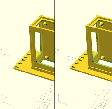
new for version 0.7 :: This setting sets the height of screw-hole standoffs (in mm) relative to the surface of the bottom of the cage.
This feature requires that the cage bottom geometry be set to Solid Bottom (No Ventilation Cutout).
cage bottom standoff screw holes
new for version 0.7 :: This setting adjusts the screw hole and overall diameter of screw-mount standoffs. Screw holes are automatically through-hole - hese extend through the standoffs and completely through the back of the cage. Standoffs are conical in shape and are 2.5x the screw hole diameter at their tops, widening to 4.5x the screw hole diameter at the base.
This feature requires that the cage bottom geometry be set to Solid Bottom (No Ventilation Cutout).
cage top bottom vent hole size
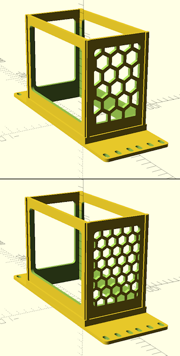
This setting sets the size of the holes of the ventilation grid. Although the measurement is in mm, what precisely is measured will vary by the grid pattern, so while this will be the actual hole diameter for hole grids, it will be the major width across openings for hexagonal grids, triangle height for triangle grinds, and so on.

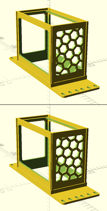
The sample picture at right shows a ventilated cage side panel - enabling ventilation for other cage sides and the faceplate will have similar results.
This setting affects different ventilation grid types in different ways - experiment with it to find usable results.
cage top bottom vent wall thickness
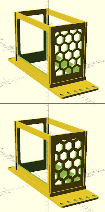
This setting sets the size of the solid portions between the holes of the ventilation grid. Higher values provide thicker walls but reduce the effective open area of the grid.
The sample picture at right shows a ventilated cage side panel - enabling ventilation for other cage sides and the faceplate will have similar results.
This setting affects different ventilation grid types in different ways - experiment with it to find usable results.
cage top bottom vent grid horizontal offset
cage top bottom vent grid vertical offset
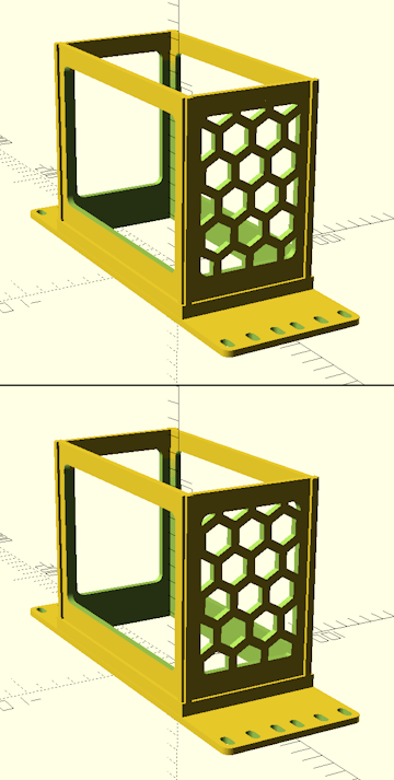
These settings change the offset of the ventilation grid in each axis. By default, ventilation grids are centered on the cage wall, and these shift that center point.
The sample picture at right shows a ventilated cage side panel - enabling ventilation for other cage sides and the faceplate will have similar results.
This setting is generally cosmetic, as it does not generally have any significant effect on ventilation or structural integrity.
cage top bottom vent grid angle
This setting changes the angle of the ventilation grid.
The sample picture at right shows a ventilated cage side panel - enabling ventilation for other cage sides and the faceplate will have similar results.
This setting is generally cosmetic, as it does not generally have any significant effect on ventilation or structural integrity.
 Back To Top
 Navigate Site
 Source Code
 Support This Project
 Community
 Legal Notices & Information
 Copyright/Trademarks